Dan Armstrong (London) wiring
1 April 2011
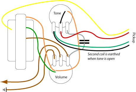
I've been asked a couple of times now for help with the wiring of the Dan Armstrong (London) sliding pickup guitar. The fact that the low-profile-pickup-sliding-on-a-rail feature was possible because it was also a low impedance pickup meant that, somewhere, there had to be a transformer. And that meant traditional electric guitar wiring schematics weren't much use.
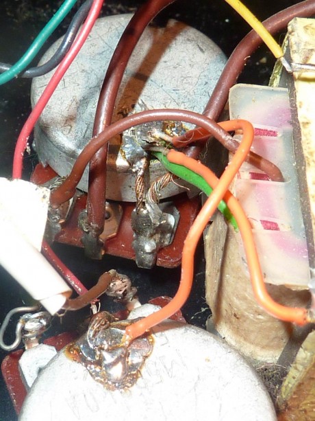
The wiring also included a coil tap, effected by running both ends of the second coil to the back end of the tone pot. With the tone wide open, the second coil was earthed, but as soon the tone darkened, the second coil kicked in.
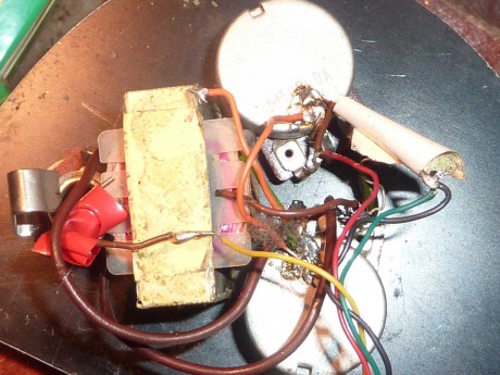
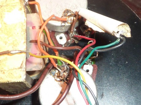
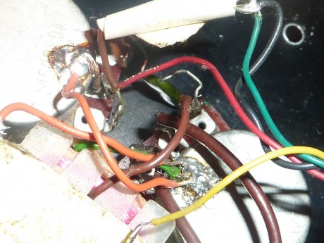
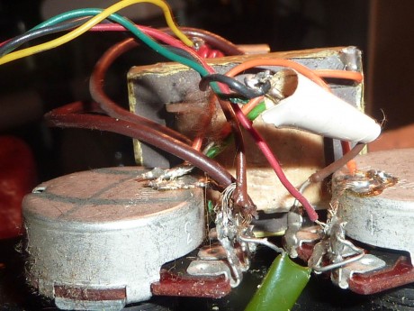
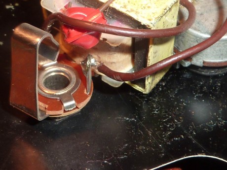
Because I have no way of knowing which wires are which on the transformer in my Dan, I'm not going to attempt to draw a proper schematic. Instead, I'm just going to draw a picture and provide a bunch of photos. I hope it's useful.

Comments
Tinu Gerber
2019.04.18 14:30
#1
That was very helpful! Thanks for sharing this cabling scheme. Worked like a charm!
Terry Relph-Knight
2020.12.13 20:56
#2
Hi,
Thanks for this useful info. Back in 1971 I worked with Dan Armstrong and I am now repairing a LONDON guitar for a friend. Some of this info was lost to me. The transformer is an auto-transformer with a ratio of 47.9 to 1. At least mine is at the temperature I'm measuring it at. As far as i know it uses the same wire gauge throughout. Dan might have been aiming at 50:1. The green wire is ground, the bare wire pin is the low Z in from the pickups and the brown is the impedance converted output. When the logo on the pickups is the right way up (Dan would often reverse the pickups) the Yellow / Green coil is uppermost toward the neck. For conventional humbucker operation Yellow is hot, Green/Black is the split connection and Red is ground.
At 1000Hz a typical DA sliding pickup measures Ls 56.46mH.
Robert Maune
2022.08.08 22:00
#3
Thanks for this. i am looking for a replacement transformer.
Add new comment